Wire Cut Precision EDM
Learn how wire EDM cuts conductive materials, how it differs from sinker EDM, and which drawing details matter for profiles, slots, and tooling components.
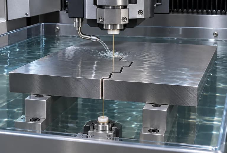
Wire electrical discharge machining, or wire EDM, cuts an electrically conductive workpiece using controlled electrical discharges between a continuously fed wire electrode and the workpiece. Dielectric fluid supports the process and helps remove debris. The wire follows a programmed path to produce a through-profile rather than removing material with a conventional cutting edge.
Electrical conductivity is a key requirement. Wire EDM can be considered for conductive metals, including suitable tool steels and hardened materials, when the geometry or material makes conventional cutting less suitable. Standard wire EDM is not a general solution for electrically insulating ceramics or plastics.
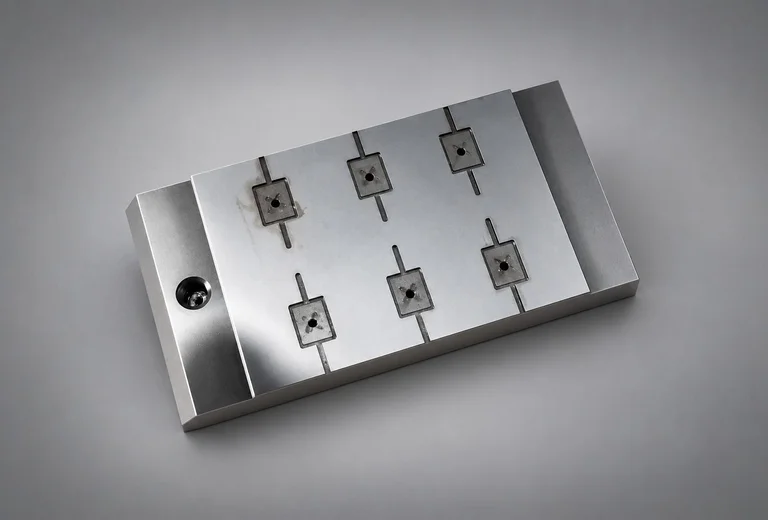
Typical geometries include through-slots, stepped outlines, punches, dies, and tooling inserts. An enclosed internal profile normally requires a start hole so the wire can be threaded. Minimum internal corner radii and cutting clearance depend on the wire and discharge gap; a perfectly sharp internal corner should not be assumed.
Preparation begins with the drawing or CAD profile, material and heat-treatment condition, workpiece thickness, datums, and critical dimensions. The machining plan considers support, the entry point, cut sequence, and removal of the cut-out section. Additional finishing passes may be appropriate for the requested accuracy and surface quality, subject to technical review.
Wire EDM and sinker EDM are related processes but serve different geometries. Wire EDM uses a moving wire for through-cuts, while sinker EDM uses a shaped electrode to form a cavity or feature. Specifying whether a feature passes through the part or ends in a blind cavity helps identify the appropriate method.
Inspection focuses on the requirements in the drawing, such as profile dimensions, slot width, position relative to datums, and surface condition. Any requirements concerning the thermally affected surface or subsequent finishing should be discussed before production. The process name alone does not establish an achievable tolerance or acceptance criterion.
For an Aiyah quotation, provide a drawing or CAD file, material, thickness, quantity, and the critical features and inspection requirements. The team can then review the appropriate process and confirm feasibility, delivery, and quotation details.
The accompanying image is an AI-generated process illustration, not a photograph of Aiyah equipment or a record of a completed customer project.